-
Notifications
You must be signed in to change notification settings - Fork 1
Home
Squidivisim is a wearable electronics project based on the concept of pattern based communication observed in some species of cephalopod. It consists of gloves containing colour sensors and accelerometers that drive addressable RGB pixels through a Arduino (FLORA) Atmega34u.
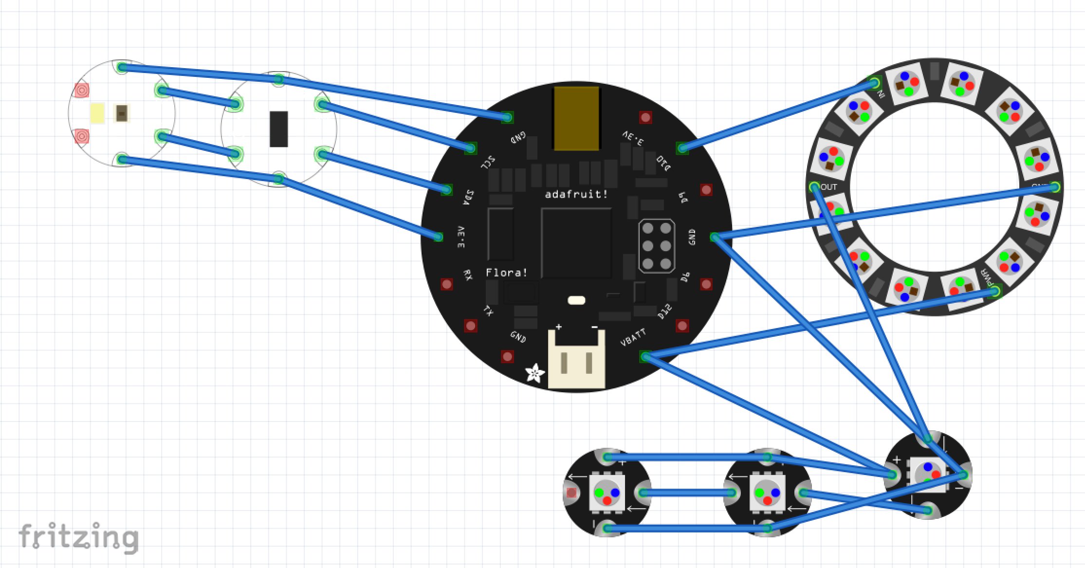
This repository contains a fritzing diagram (and a JPEG screen cap of the diagram in case you don't have Fritzing, which you should because it's awesome) and the Arduino code.
You’ll find the code full of inconsistent spelling of the word colour, because I’m not American, but many of the libraries were written by Americans and I refuse to spell colour wrong unless I have to.
Here’s how it works, when you first start them up, the colours on the RGB strips are generated based on the values generated by the 3 axis accelerometer, if you’ve ever worked with accelerometers, you’ll know they’re damn complicated to work with, every axis produces a value representing the force of gravity on that axis, if you tilt the sensor, the force of gravity acts upon them differently, if you make movements you can measure motion relative to gravity but not in any useful or reliable way.
The accelerometer is however sufficient for generating colour values based on movement assuming you don’t want anything specific, I use a circular table of values to generate smoothing on the parameters, and I use Euclidean vector math to produce a magnitude of movement, which is used to translate dramatic hand gestures into a switch between generating patterns using the colour sensor and generating patterns using the accelerometer.
When you switch to colour reading mode, the colour sensor will periodically enable a white LED and take a reading, then the pixels will fade to the sampled colour. It also stores that sampled colour in a small table, it’ll fade between these samples to generate patterns based on the colours you sampled.
To switch back to accelerometer based patterns, just make another drastic movement, the accelerometer reading never stops, they’re just not used for generating colours when you’re in colour sampling mode.
The colour pattern code will work with any number of pixels, just change the first parameter in the NeoPixel strip declaration up the top. Many other parameters are easily tweaked, the code is full of comments to make it easy to follow.
The Arduino code for this project has the following dependencies:
Adafruit Arduino IDE Contains drivers for the FLORA Atmega34u micro controller from Adafruit)
Adafruit Unified Sensors Library Nice standard sensors library, hardly used in this project other than as a dependency for the LSM303DLHC.
Adafruit NeoPixel Library The Adafruit WS2812 based addressable RGB Pixel library, a fairly nice and simple way of driving adressable strips, I've used others but seeing as everything else in this project is Adafruit, I figured it would be best to use their library for driving the RGB pixels.
Adafruit LSM303DLHC Library The Unified Sensors version of the LSM303 Accelerometer and Compass module library.
Adafruit TCS34725 Colour Sensor Driver The Adafruit library for the TCS34725 RGB colour sensor.
Here are some pictures of the prototypes.
The front side showing the colour sensor in the palm of the hand.
The back side showing a NeoPixel ring, accelerometer and FLORA micro controller.
And a screen cap of the Fritzing diagram.


