Waveshare 3.5" LCD hack for backlight control
This Waveshare 3.5" LCD is pretty common all around. It is relatively cheap and of decent quality. However it doesn't support brightness (backlight) control. Below you will find how I hacked my way to retrofit this functionality into my LCD. Mind that this LCD can internally differ a lot between batches, model years or whether a LCD is counterfeited or not.
Before I started doing it my way I dug thru "internets" and found that the following instructions were helpful, but my LCD model was different:
The schematic of my LCD - I think it is pretty relevant to what I have.
So, please think twice or more before you decide to make any changes that will void your warranty (if you have one :) or even kill the display. Make sure your version looks the same as mine, if not check above links - maybe they will be more relevant.
- soldering iron
- sharp cutting knife
- some wires
- a multimeter might be helpful
- some basic electronic parts (see Brightness module below)
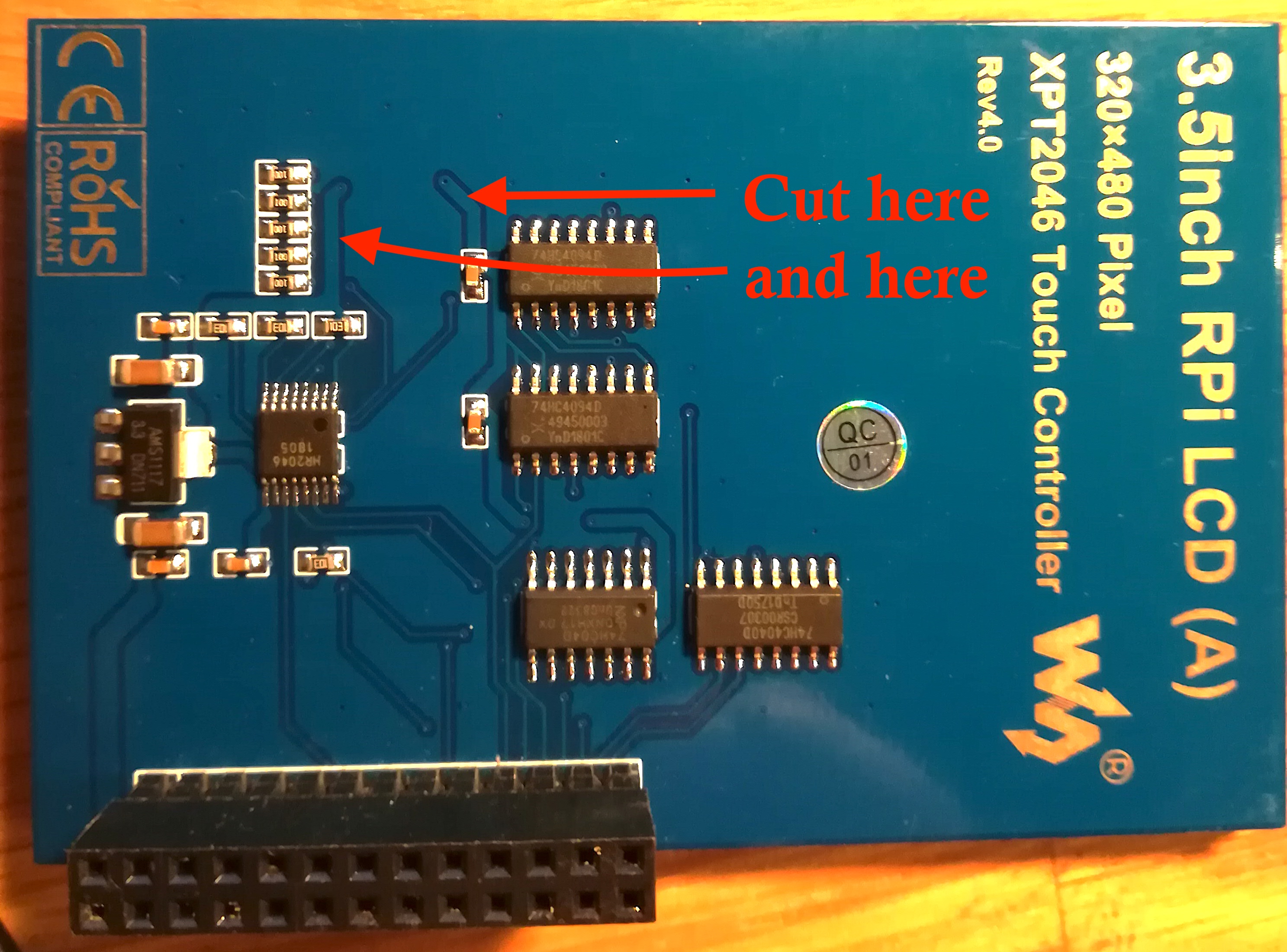
- compare the photos below with the LCD you have
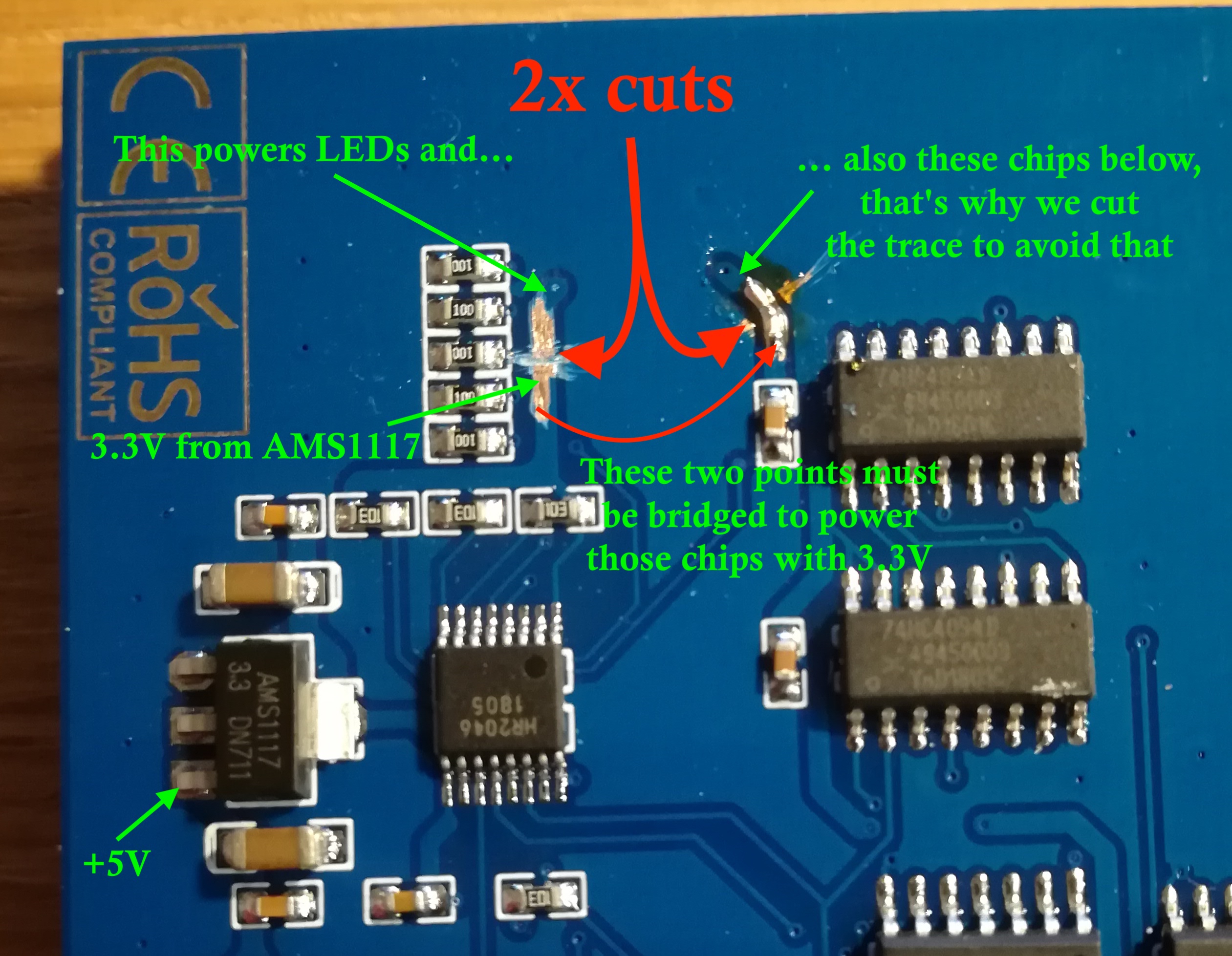
- identify the right traces to cut - we simply cut off 3.3V supply for LEDs (and for decoding circuits, but keep calm and read on)
- remove bits of blue film to have good soldering points
- first, you have to solder a bridge wire for decoding circuits as they used the same 3.3V as for LEDs
- solder two wires as illustrated below - will use them to control (via PWM) the brightness of backlight by using NPN transistor -don't short circuit these two wires (!) as it will directly supply 5V to LEDs - this won't be healthy for them. If you want to test before going further, either use multimeter or close them thru a resistor (you need to drop at least 1.5V @ 70-100mA so calculate its resistency).

- the list of electronic components:
- optocoupler, for example 4N25
- NPN transistor, for example 2N2222
- resistors: 10ohm, 100ohm, 220ohm
- see schematic here how to connect those things together
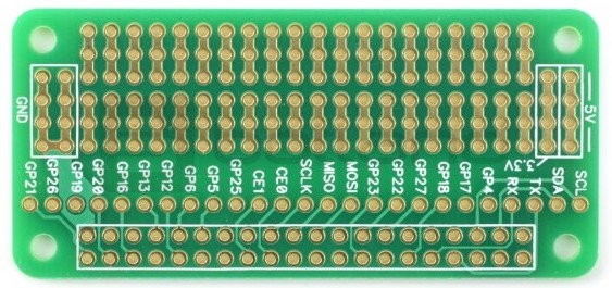
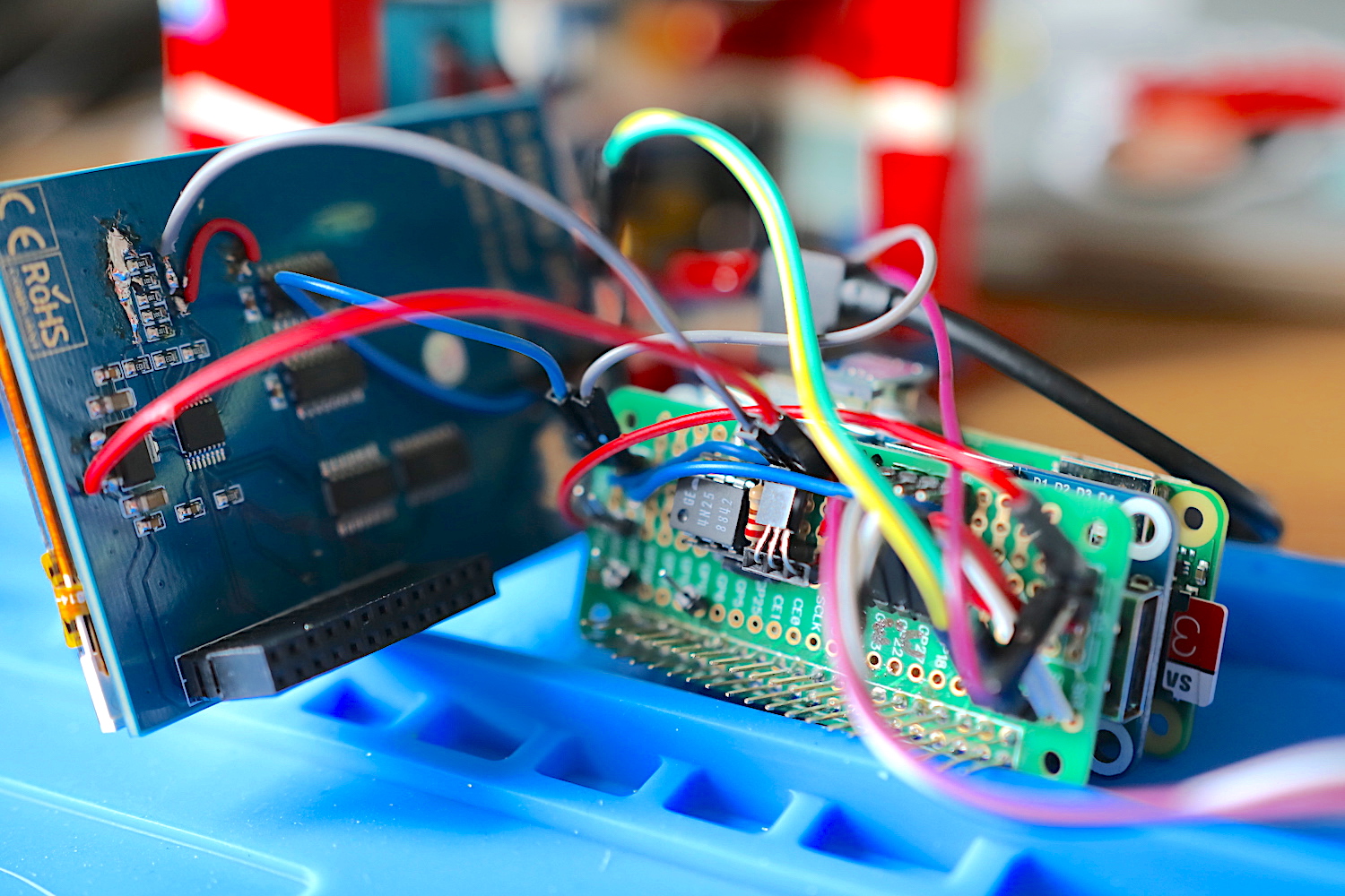
- you can use this Prototype board for RPi Zero to solder this module together. As you can see this proto board has enough space to do that:
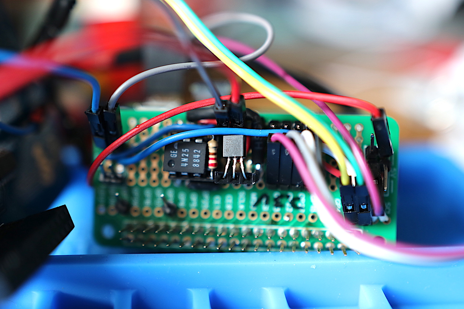
This simple module controls the base of NPN transistor through Optocoupler which in turn is controlled by GPIO 12 (or any other that is PWM capable). You may ask why we wired 5V to control those LEDs - this is because transistor's voltage drop (~0.6V) when using the orignal 3.3V would place those LEDs outside of their minimum voltage requirements. So, having 5V (unregulated :/ - screen may slightly dim from time to time) we have a base for that voltage drop, but this voltage drop is still not enough to sefely operate the backlight - hence that small 10ohm resistor.
This is how I did it (I used 8PIN stands and 1x3 2.54 female socket to easily replace either opto or transistor):
If you succeeded, then in the RPi console you can run:
gpio -g mode 12 pwm-
gpio -g pwm 12 value(value between 0-1023) -
gpio pwm-ms- it seems this mode of PWM works better here - I think either opto or NPN is not quick enough in balanced mode (a default mode). In balanced mode the value as low as 400 makes the backlight to shine 100%.
To automatically dim the LCD in function of ambient light I used I2C module TSL2561 and this script to nicely control the backlight (with theater dimming effect): brightness.sh. The script can also be signaled with HUP to temporarily increase brightness instantaneously (it will return to automatic mode after ~60seconds or when CONT is sent) - useful for the voice assistant when invocation word is heard.