
![]()
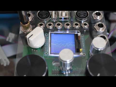
open source hardware and software for a teensy 4.0 eurorack shield
These circuit boards provide the peripherals necessary to interface a teensy 4.0 with stereo line audio and eurorack modular equipment.
- specifications
- open source software-stack
- support
- social media
- printed circuit boards
- panel design
- assembly technical drawings
- videos
- versions
- todo

- microcontrollers:
- 600 Mhz ARM cortex m7 ( teensy 4.0 board )
- SAMD21 32bit 48Mhz micro-controller (based on arduino mkr1000)
- audio: multi-channel audio codec ( 6-in / 8-out 24-bit sound card - CS42448 )
- the audio codec circuit originally started as a discussion on quad audio channel outputs and a pcb design integrating teensy and cs42448 from Paul Stoffregen on pjrc forum
- analog control voltage ins/outs: -10V to 10V 16bit/sample, 8 x inputs and 4 x outputs ( ad7606, ad5754 )
- display: ST7735 128x128 16bit-color tft display
- breakouts:
- microSD card socket,
- USB host/device,
- midi in/out,
- knobs (4 x pots, 3 x RGB encoders w/switch)
- gpio: 4 x configurable 5v logic inputs/outputs. PCA9536
- panel: 24HP aluminium panel mounted for eurorack case
- programability:
- write arduino compatible c/c++ firmware & program using arduino/teensyduino
- arm gnu toolchain downloads
- teensy audio library
- MIT license unless otherwise specified on a per file basis.
- All schematics and boards are created using Kicad
- All mechanical designs are created using FreeCAD
- Some images have been rendered using Blender 2.81
This project is a work-in-progress! The functionality has been tested and are working at a basic level.
There are some improvements I'd like to make later
- improve noise to signal ratio on pots on breakout board.
- add 4x jack sockets for analog output of knobs on breakout board.
- use 3.5mm jack sockets (as well as standard midi din connectors) for midi in and out.
- switch to active audio input and output circuitry, allow switchable 0dB / 12dB gain, for guitar signals.
- let me know if you're think there something else that can be improved, added, removed.
There is a journal of my progress, journal.md
What you can do if you like to see progress with this project?
- star this repository (means you need a github account - go for it!!)
- subscribe Nic N on youtube
- download kicad and freecad, clone this repo, make improvements, commit & send pull-requests, and raise issues...
- standard double layer printed circuit board
- thinkness: 1.6mm
- minimum trace: 6 mil
- minimum clearance: 6 mil
- dimension: 118mm*102mm
- socket to connect teensy 4.0 board
- cs42448 audio codec
- 3 x stereo 6.35mm TRS jack inputs
- 4 x stereo 6.35mm TRS jack outputs
- pin sockets to connect breakout board
- PCA9536 gpio


- standard double layer printed circuit board
- thinkness: 1.6mm
- minimum trace: 6 mil
- minimum clearance: 6 mil
- dimension: 110mm*111mm
- 8 x 3.5mm jack socket for analog control voltage inputs
- 4 x 3.5mm jack socket for analog control voltage outputs
- 4 x 3.5mm jack socket for 5v GPIO (general purpose inputs or outputs)
- midi in/out DIN sockets
- usb device/host
- USB-B: USB device mode
- USB-A: USB host mode
- micro-SD card socket
- 4 x linear pots
- 3 x RGB rotary encoders with switches
- SAMD21 32bit 48Mhz micro-controller for pots and rotaries
- Based on Arduino MKR Zero board (can be programmed through standard arduino ide)
- Communicates with mainboard via standard serial uart RX and TX lines.


- Teensy 4.0 eurorack shield design intro

- 0v to 10v control voltage input, output and display using teensy 4.0

- DIY assembly build - teensy 4.0 eurorack audio module

- assembling teensy eurorack shield

- assembly timelapse

- Eurorack digital audio modules powered by teensy micro-controller
- side-channel stereo audio separation with teensy 4.0

cleanup, minor improvements, and reduce number of distinct components
- breakout board:
- changed C6 (1nF) from 1206 to 0805 to match C2 - reduces number of unique components by 1
- mainboard
- cleanup of footprints to reduce number of distinct parts
- removed pull-up resistor on AD_RESET signal
- increased size of power traces to 350 mil
status:
  15/03/2020:
    * placed order with JLCPCB.com, total £63.33
      * 20 x mainboard @ v1.8.1 + top stencil (£15.53 + £5.38 )
      * 20 x breakout @ v1.8.1 + top & bottom stencil (£15.69 + £10.76)
      * shipping: £15.97
status:
 * 25/02/2020: placed pcb order with jlcpcb
 * 28/02/2020: order dispatched
 * 02/03/2020: pcbs arrived, but parts are still waiting to be delivered.
 * 08/03/2020: mainboard v1.7 + breakout board v1.8 - all features tested successfully.
- breakout board:
- fixed: midi DIN connectors pin 4 and pin 5 switched
- mainboard remains same at version 1.7
status:
 * 26/01/2020: placed pcb order with jlcpcb
 * 22/02/2020:
   * boards assembled, sanity checks pass, form factor is good - no known issues so far
   * adc AD7606 tested briefly, looks better
   * usb-device type-b socket tested successfully, serial-over-usb and programming connection seem good
 * 23/02/2020:
   * issue with midi in/out circuits
     * pin 4 and pin 5 on the midi din connectors appear to be switched on both rx and tx midi sockets
     * tx may need logic level shifter or buffer.
- breakout board:
- fixed: net 3v3 collides with net VIN
- LDO footprint imported from eagle is causing DRC check to succeed even though the two traces collide
- fixed: net 3v3 collides with net VIN
status:
 * 10/01/2020: placed pcb and stencil order with jlcpcb
   * total is £36.05
     * Shipping Charge: £13.05
     * Merchandise: £23.00
       * 2 x aluminium stencils: £10.66
       * 2 x 5pcs x pcboard: £12.34
 * 12/01/2020: order dispatched
 * 24/01/2020: pcboards and stencils arrived.
- circuit corrections
- adc: corrected AVSS net, should have been VSS
- removed unused through-hole pads from underside of teensy board.
- physical
- merged knobs-controller and top-breakout pc-boards into single board
- tft display rotated 90 degrees
- sd-connector socket rotated 90 degrees
- replaced fine-pitch FPC/FFC connectors with standard 0.1' pin-headers and sockets, allowing boards to connect physically
- circuit corrections
- corrected: knobs-controller: tx/rx nets were not connected to socket
- enhancement: extra uart exposed
- allows serial communications via the unused pins in the eurorack power-connector
- 2 jumper-switches added to switch between master/slave - (rx/tx cross-over configuration)
- connects to RX7, TX7 (pins 28, 29) on the under-side of the teensy 4.0 board
- enhancement: adc: AD_RESET net connected to micro-controller
- enhancement: introduced PCA9536 i2c GPIO integrated-circuit to free-up some pins on the micro-controller
- General
- cleanup / refactor footprints, replace footprints and symbols imported from eagle with kicad equivalents
- Breakout board for rotary encoders and pots
-
Order -
Assemble - software
- document
- certify
-
-
panel-
measurements -
design
-
- finalize circuits / boards
-
testing-
CS42448 audio codec-
Audio input -
Audio output
-
-
control voltage input -
control voltage output -
gpio (input & output) -
usb host -
usb device -
midi in/out -
st7735 display -
sd card extension & adapter
-
- Document
- order & build process
- software process
- Firmware
- Sliced audio loops
- Midi looping
- testing automated build and packaging
- github.com/pwuertz/kicad_picknplace_assistant
- github.com/productize/kicad-automation-scripts