use compute instead of geometry shaders #5
Comments
|
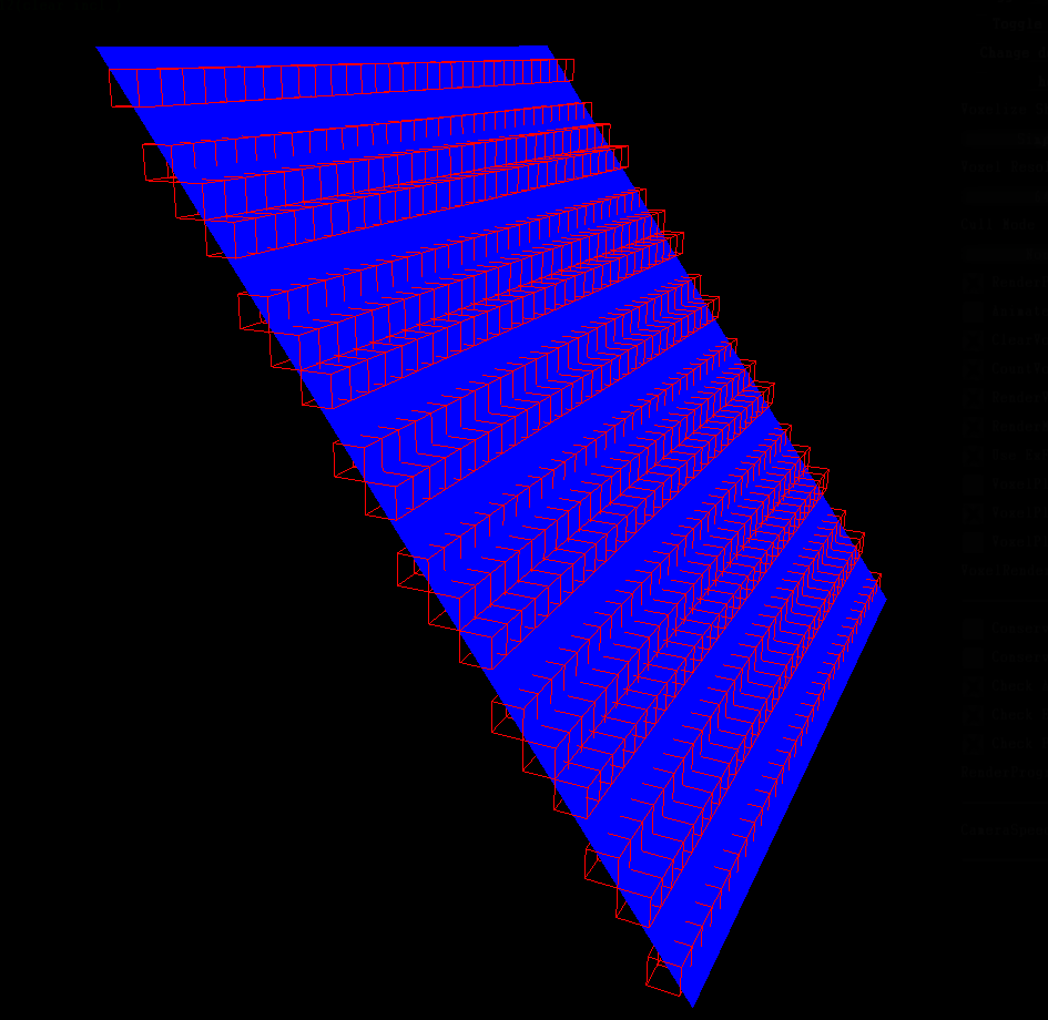
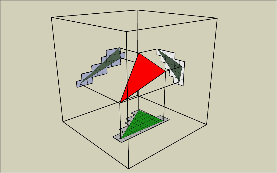
My voxelization implementation is based on this source, which provides a good insight on the subject matter. The thing about voxelization that it is just as simple as render object to the screen, but instead of writing color to the screen buffer, we collect the depth value and output to a volume buffer. The problem arises when the depth gradient of a particular triangle is high ( To solve this issue, we just need to project the triangle onto a plane where the projection area is the largest. That means we would need 3 rendering passes to project the scene into 3 different axes. The nice thing about the geometry shader is that we can combine all the 3 rendering passes into one. Because the voxel volume is a cube and the projection axes X, Y, Z are orthogonal to each other, we only need to swizzle the X, Y, Z components of vertex position in voxel space. This can be easily done in geometry shader by calculating the triangle normal and selecting the corresponding projection axis. You can see it here: Unity-SRP-VXGI/Runtime/Shaders/Basic.shader Lines 206 to 257 in 5e3acd7 About the problem on Metal API, without geometry shader, we just use 3 rendering passes to voxelize the scene, which might triple the processing time. I ran the GPU profiler, and the processing time of voxelization stage with geomertry shader is quite trivial with respect to other processing stages. So I don't think tripling the processing time doesn't matter much. If I were to implement this on compute shader, I doubt that this would add more complexity to the project and re-invent the wheel. And I'm a simple man, I hate complexity (╯°□°)╯︵ ┻━┻ |
|
Btw, about the geometry shader performance, your source was written back in 2015, which is quite old. The developers from the game Factorio (which I'm a fan of) tested geometry shader on variety of PCs last year and found that new GPU executes geometry shader better than the older generation. Apart from the processing performance, we have to consider the amount of work into organizing the data before passing them to the voxelizer. The final result is not only to detect which voxel the scene occupy, but also have to gather the material properties for that voxel in order to perform voxel cone tracing and indirect lighting at the later stages. For now, I will stick to the current implementation because it is more convenient for handling inputs, outputs and vertices transformation. |
|
It is good to know they improved the performance of geometry shaders. AFAIK, the compute-shader method does not require three passes, and it does not change the code much. The geometry shader calculations simply move into a compute shader. It takes the same input, it produces the same output. Instead of one draw call, you get one compute call and one draw call. This is described in the third link I posted.. here: https://stackoverflow.com/questions/50557224/metal-emulate-geometry-shaders-using-compute-shaders
This developer complains that the compute-shader version takes double the memory, because it has an input buffer and output buffer. Perhaps there is a way around this by using the same buffer for input and output from the compute shader. |
|
Here are 2 problems: 1. Double-memory because of input and output buffersUnity uses a list of vertex positions and a list of triangles to store Mesh data. The list of triangles contains indices that refer to the list of index positions. This data structure helps reduce memory footprint because a same vertex position can be referred by multiple triangles. Now, we need to voxelize the the mesh data. We need to separate the triangles, and "rotate" them to face the projection plane accordingly. This means that vertex positions on the some of the triangles changed. For example, a vertex, that is used by 2 triangles, can be separated into 2 vertices with different position. Therefore, the output mesh data might be different than the input mesh data if any of the triangles is rotated. This is the reason why we need separate input buffer and output buffer to process mesh data. 2. Provide the compute shader with vertices dataOnce we get the meshes that need to be voxelized, we need to pass these mesh data to the compute shader. We can do something like this, which uses I don't know about this, but I think Unity has an internal mechanism that is used to transfer, not only mesh data, but also UVs, textures, normals and tangents data to the internal render pipeline, which is very fast. This mechanism is used by In conclusion, we need to find this fast mechanism to pass renderer data to the compute shader. Otherwise, issuing a draw call 3 times is probably faster than just moving the data back and forth. That's what I think about the problems. Moreover, in my experience, I think that compute shader is very good at generating mesh for procedural draw call, not modifying the existing one. This example uses both compute shader and geometry shader to render grass affected by the wind and tramples, which is kinda cool and demonstrates the power and usefulness of geometry shader. |
|
I understand. Thanks for your response! In the case of #2, I can't find any discussion of Probably better to move to the new SRP in 2019 before worrying about Mac anyhow. It is interesting that Unity Mac OpenGL supports Geometry Shaders but not compute shaders, and Unity Mac Metal supports Compute Shaders but not Geometry Shaders. |
|
I think that it is pretty obvious that people don't discuss about it. The thing about this is that you have to move the data from the CPU memory to the GPU memory through the computer data bus. If you have ever studied computer architecture, you would have know that CPU usually wait for I/O because fetching data from RAM is usually slower than the CPU executing instructions in 1-2 cycles. The same thing applies to GPU. GPU with the architecture, designed to be able to execute instruction fast in parallel, might actually wait for the data transfer from RAM to the GPU memory. Is there a way to solve this issue? Yes, we just need to find a way to access mesh data that is (probably) already available on the GPU. Unity does have You can test the Unity-SRP-VXGI/Runtime/Scripts/SRP/VXGIRenderer.cs Lines 182 to 203 in 2f4bce1 Unity-SRP-VXGI/Runtime/Shaders/VXGI.shader Lines 216 to 309 in 2f4bce1 Another time, I was developing the light injection mechanism by using P/s: use the CPU/GPU profiler and frame debugger to see the processing that of these operations. Try uploading an array with the length of 1.000/10.000/100.000/1.000.000. |
This post saids that is because Apple refused to support modern OpenGL versions 🤣 |
|
Yes, I understand Compute Architecture. I am a 45 y/o Computer Engineer Programmer. I understand GPU and CPU hardware much more than I understand Unity. Of course transferring data to the GPU takes time. However, it takes the same amount of time to send the data to the GPU whether it is into a ComputeBuffer or a VB/IB buffer. This is normally done ahead of time, when the mesh is created, not every frame. I think I understand now that Unity is hard-coded to put Mesh data into VB/IB buffers. And even though all graphics APIs have mechanisms for Compute Shaders to see VB/IB buffers, Unity Compute Shaders have no such mechanism. At first I thought something like Instead, each Renderer would need to be drawn through a compute-shader -- by binding VB/IB data to a compute shader, call the compute shader, then call Is it possible to rewrite a custom version of SRC.DrawRenderers()? If so then I think a way to hand VB/IB data to a compute shader would be sufficient? I made a post on the SRP feedback thread. Looks like Mac support may be easier in a Xenko port. As for |
|
So, we will put this issue on hold. Meanwhile, are you interested in reviewing my PRs when I modify the code? In the future, I want to restructure the codebase properly to make it easier for others to understand or collaborate on this project. |
|
Yes, I would be happy to! Do you plan to make improvements next? or update for 2019 SRP? If the latter, it may make sense to make a release/tag/branch for 2018.3 first. |
|
Currently, here is my plan:
|
|
I wish to improve the quality as much as I can before putting a version tag on it. |
|
The soft shadows they get in NVidia VXGI 2.0 / VXAL are pretty impressive. I think frosted voxel refraction can also be quite interesting in VXGI, as in this example from Armory3d:
|

|
Ah yes, refraction, I almost forget about it. I implemented refraction before, it only works if light pass through a single layer of glass to the camera. Because the glass acts as a "lens" to "see" the voxel world, it doesn't work with multiple layer of glasses. I want to implement subsurface scattering as well. Let's add them to the list. About the soft shadow, I think it is pretty easy, we just need to change the visibility function from ray tracing to cone tracing. |
|
Can you go into github project settings and enable the Wiki? This is an easy place to keep some simple installation instructions and notes. Also, github has a nice "todo list" feature, where you use
|
|
Yes, I already have Wikis enabled. About the plan, I will have it setup inside Github Project page. I will add you to the list of collaborators so you can see it. |
|
I've been reading the code, trying to understand it.... does it do Toridial addressing for the voxel buffer to reuse parts of the voxel buffer from frame-to-frame? As described here?
|

|
I have just reorganized the file structure with minimal code modifications. Hope it doesn't affect you much. I didn't implement Toridial addressing. I have never heard of clipmap until now. This is a very interesting resource you have here. I will spend the weekend researching it. One question: is it applicable for anisotropic voxel cascade (implemented in "The Tomorrow Children")? Because I'm planning to implement that. |
...or at least support compute shaders as an alternative...
...because (a) it'll work on Metal / Mac, and (b) the performance of geometry shaders sucks
https://forum.unity.com/threads/ios-11-metal2-has-no-geometry-shader.499676/#post-3315734
https://stackoverflow.com/questions/50557224/metal-emulate-geometry-shaders-using-compute-shaders
The text was updated successfully, but these errors were encountered: